RD® pile wall drilled extremely near to old buildings in K6, Helsinki
Skanska is developer of a new office building called K6 in Helsinki, Finland. Three underground floors just next to existing buildings mean demanding excavations. RD pile wall is used as permanent retaining wall to support excavation and to create final wall structure.
Since Skanska is developer of K6, Skanska will fund and contract the building. Retaining walls, excavations and foundations are done by Skanska Infra Oy and other structures are done by Skanska Talonrakennus Oy.
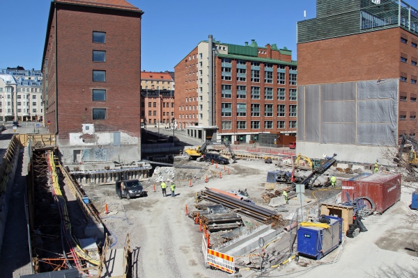
Figure 1. Skanska’s construction site
Ground conditions at the site are demanding for deep excavations and installation of retaining walls. On top of natural soil layers is varying fill layer consisting different kind of granular soils. Natural soil layers consist mainly of sandy and silty soils. Below these soft soils is a very hard moraine layer and the bedrock. First choice for retaining walls was secant pile wall. Skanska made an installation test with sheet piles and noticed moraine layer to be too dense and hard to achieve economical installation speed for secant pile wall. This lead to change the retaining wall type to RD pile wall.
Before the final decision of the type of the retaining wall was done, SSAB’s technical support was participating in finding the most suitable solution. “We have found SSAB’s technical support very useful in this project”, says Pasi Mäkinen, Project Manager from Skanska Infra Oy. “During the design phase of the project we had couple of technical meetings with designers and SSAB. We presented our ideas to both designers and SSAB and got good feedback and new ideas. Some ideas needed little fixing, but due to these meeting we ended up with highly sophisticated solution for this very demanding project.”
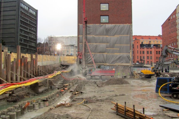
Drilling of RD pile wall began at November 2016 and last pile was drilled in March 2017. No problems were encountered during installation. First anchor level at the top of the piles is now ready and excavation has begun.
Figure 2. Drilling of RD pile wall at K6 site
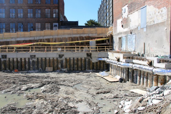
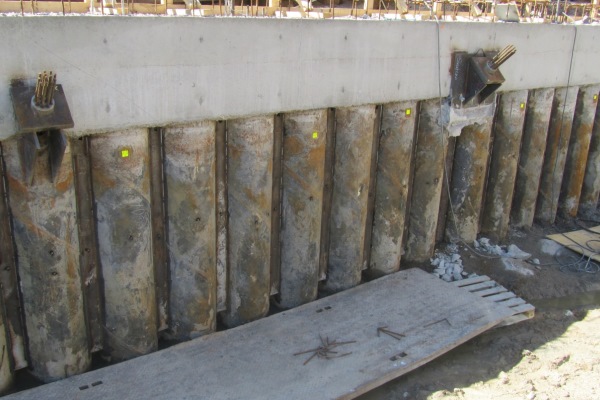
Existing buildings nearby caused some special procedures for making of RD pile wall. First building, on left hand side in Figure 1 is founded on top of natural soil layers. To prevent possible settlement of the building a jet grouting wall was done just beside the old foundations. This jet grouting extended from top of the bedrock all the way to the bottom of the foundations. RD pile wall was drilled as close to the old building as possible, the centers of the RD piles are only 1200 mm from the surface of the old façade, shown in Figure 3. Jet grouting was also used to protect old concrete piles of another existing building, on right hand side in Figure 1. In this case jet grouting was used only close to bottom end of concrete piles. The function of this jet grouting was to ensure end bearing resistance of the concrete piles when RD pile wall is drilled close to them. Both buildings have been monitored during the drilling of RD pile wall, and monitoring will continue during the excavation phase.
Figure 3. RD pile wall drilled just next to old building
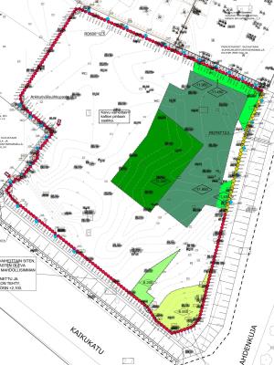
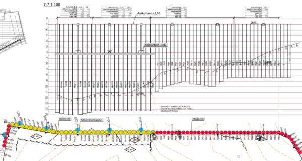
RD pile wall is made of two pile sizes RD600 and RD700, shown in Figure 4 in red and yellow respectively. RD700 is used in area where the surface of bedrock is at deepest. SSAB delivered 233 RM-RF interlocked RD600/12.5 piles and 32 RM-RF-interlocked RD700/12.5 piles. All piles were S440J2H steel grade. The delivery included in total over 700 tons of steel and 3 500 meters of RM-RF interlocked RD piles.
Figure 4. Drawing of RD pile wall (red piles = RD600, yellow piles = RD700)
All piles of RD pile wall were drilled at least 4d (2.4 m for RD600 and 2.8 for RD700) into the bedrock. In areas where bedrock surface needs to be lowered by blasting, drilling depth was deeper. After drilling, the annulus between pile pipe and bedrock was grouted through injection channel in RF interlock profile to achieve a rigid connection between pile toe and bedrock. The use of rigid connection between RD pile wall and bedrock has made it possible to reduce the amount of support levels and number of anchors significantly. In some parts of the 10 m high RD pile wall there is only one anchor level at the very top end of the pile wall.
Figure 5. Anchor level at the top end of the RD pile wall
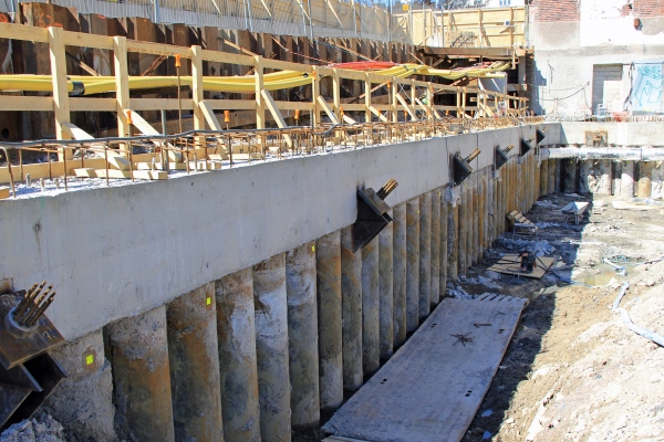
The rigidness of the connection between pile toe and bedrock is ensured by monitoring during excavation. The deformation and displacement of the RD pile wall is monitored with tachymeter from prisms glued to the piles (prisms can be seen as yellow squares in piles in Figures 5 and 7). Measured deformations are compared to theoretically calculated deformations to ensure correct behavior of the wall structure. Additionally some of the anchors are equipped with load cells to monitor exact anchor forces in real time. All anchors are temporary anchors. In final stage the concrete slabs will function as a support for the RD pile wall.
Regardless of the rigid connection at the pile toe, more than one anchor level is needed in some areas of the wall. In these areas a special design of the wall is used. To avoid drilling of holes for anchors through the RD piles, some gaps were left between RD piles. These 200 mm wide gaps were filled by jet grouting to ensure watertightness of the wall, shown in Figures 4 and 6 in blue. In these areas the anchors are positioned at same locations on top of each other and holes for anchors are drilled through jet grouting columns. These discontinuities in the RD pile wall have been taken into account when calculating the actual bending resistance and stiffness of the RD pile wall.
Figure 6. In some areas of the wall more than one anchor level is needed.
Watertightness of interlocks during construction period is achieved with bitumen sealant. Sealant material was added to female interlock profile at SSAB’s pipe mill. To ensure watertightness for the whole service life of the RD pile wall, a steel plate will be welded in front of all interlocks, see Figure 7. The gap between interlock and steel plate will be filled by grouting. This steel plate and grouting technique is used also in places where jet grouting columns are installed between RD piles.
Figure 7. Steel plates welded in front of interlocks
After excavation the bedrock surface in some areas is at too high level and it needs to be blasted way. These areas are sown with green color in Figure 4. In the corner of the building (lowest corner in Figure 4), some 3.0-3.5 m of bedrock will be blasted away just next to RD pile wall. Due to over sizes drill bits the bedrock and pile pipe are not in contact with each other, but still this rock blasting will be done with precaution.
In final state the RD pile wall will not take only the lateral loads from soil pressure, it will also supports the façade of the building on top of it. RD pile wall will remain as a final wall surface at the underground floors. The surface of the piles will only be sandblasted and painted to achieve good looking surface. Sufficient resistance of the RD pile wall in case of fire is ensured by concreting all piles and by installing reinforcement to every fifth pile in the wall.
- Main contractor, foundations: Skanska Infra Oy
- Geotechnical design: Sito Oy
- Drilling contractor: Sotkamon Porakaivo Oy
- RD pile wall supplier: SSAB Europe Oy
Attachments
Category and tags