Electric vehicle battery enclosures & protection: Docol® EV Design Concept

In response to the unique Body-in-White challenges posed by battery electric vehicles, SSAB has developed a new, “virtual platform” to help foster the next generation of design solutions made from Docol® advanced high strength steels.

Watch the animated short

A virtual platform for EV design solutions

The Docol EV Design Concept demonstrates ways to cost-effectively improve the safety, weight, and space utilization of electric vehicles, optimizing body geometries with AHSS steels for the most important load paths. The EV Concept currently includes innovative ideas for:

  • EV battery enclosures made from 3D roll-formed AHSS steel
  • Optimizing floor cross beams to minimize crash intrusion on EV battery packs
  • And optimizing energy-absorbing beams for the EV’s sill (rocker panel)

Reducing the height of EV battery enclosures using 3D roll-formed profiles

EV battery box undergoing side pole impact crash simulation.

Figure 1: This partial prototype of an electric vehicle battery case uses key ideas from the Docol EV Design Concept: energy-absorbing sill beams (shown here after a side pole impact test); energy-transferring floor cross members; and 3D roll-formed battery carrying structure (see Figure 2 below). The side impact test requires there be no intrusion into the battery pack. The lowest possible weight for this EV battery container is 75kg for a battery pack of 1742 x 1320 x 120mm size. (Note: in this article, we use the following terms interchangeably: EV battery box, enclosure, case, casing, container, and housing.)

EV battery case concept: exploded view of construction

Figure 2: Exploded view of the Docol EV Concept battery housing design.

A unique component of the Docol EV Design Concept for battery boxes is the lower load-carrying structure made from 3D roll-formed profiles arranged in a mesh pattern. The mesh maintains a specified distance between the enclosure’s bottom plate and its battery tray, ensuring sufficient protection of the battery from impacts from the Z-direction (that is, crash impacts coming from below the car).

If you made the mesh using a 2D roll-formed profile that is perpendicular to a similar 2D profile, you double the mesh’s height. This problem can be eliminated using 3D roll-forming technology. In a 3D roll-forming machine, the rolls can move in all directions during the forming process. So you can create one part of the profile that is fixed and one part that is flexible, as shown in Figure 3. Then one profile can be placed perpendicularly to a similar profile – that is turned upside down – without doubling its height in the Z-direction.

Unbroken load paths for strong EV battery protection

3D roll-formed 1700 martensitic steel beams protecting EV battery pack

Figure 3: The blue beams below the passenger compartment in this illustration are the bottom “mesh” structure of an EV battery box – made from the cross pattern of 3D roll-formed beams in Docol 1700M (martensitic). The profiles in the X-direction are the same as in Y-direction, but turned upside down to reduce the mesh’s height by a factor of two.

3D roll-forming 1700M steel for EV battery protection

Figure 4: 3D roll-forming technology and photo from Ortic AB of Borlänge, Sweden. www.ortic.se

Because the grooves are fixed along the length of the beams, the load paths in X and Y directions are unbroken and therefore the strongest possible. The 3D roll-forming production is fully flexible, which means that the distance between each cross beam of the load-carry structure can be changed through the 3D roll-forming machine’s software. 3D roll-forming is cost efficient and highly flexible – it also enables a high level of material utilization.

EV battery tray contains post-crash cell leakage

The EV battery boxes’ tray is made from soft steel, drawn to form completely vertical (90°) side walls that optimize the space for the battery pack. The tray also prevents the EV battery cells from leaking into the environment during and after a crash.

A frame around the battery tray provides impact protection as well as a stabilizing structure. The frame’s profiled sides are made from Docol martensitic 1700Mpa and are fabricated using conventional 2D roll-forming, with cost-efficient die-cast corners connecting the four sides.


FAQ for the Docol® EV Concept battery enclosure

Expand all

What is the estimated weight for the entire EV battery enclosure?

75 kg is the lowest possible weight for this EV battery housing for a battery pack of 1742 x 1320 x 120mm size.

What is the function of the EV battery tray?

EV battery trays hold the battery module or pack and, in the case of a crash, contain the battery cell’s fluids from leaking to the environment.

What makes the EV battery enclosure’s design impact resistant?

The EV Concept’s battery protection comes from the enclosure’s side frame, the lower load-carrying structure, the sill beams, and the floor cross beams.

Are UHSS steels better than aluminum for electric vehicle battery enclosures?

While both aluminum and UHSS can be very good, when used in robust designs, at protecting EV batteries, reducing costs is a key priority for EV OEMs. UHSS is significantly less expensive than aluminum and much less carbon intensive to make.

Designing an energy absorbing AHSS beam for the EVs sill rocker structure

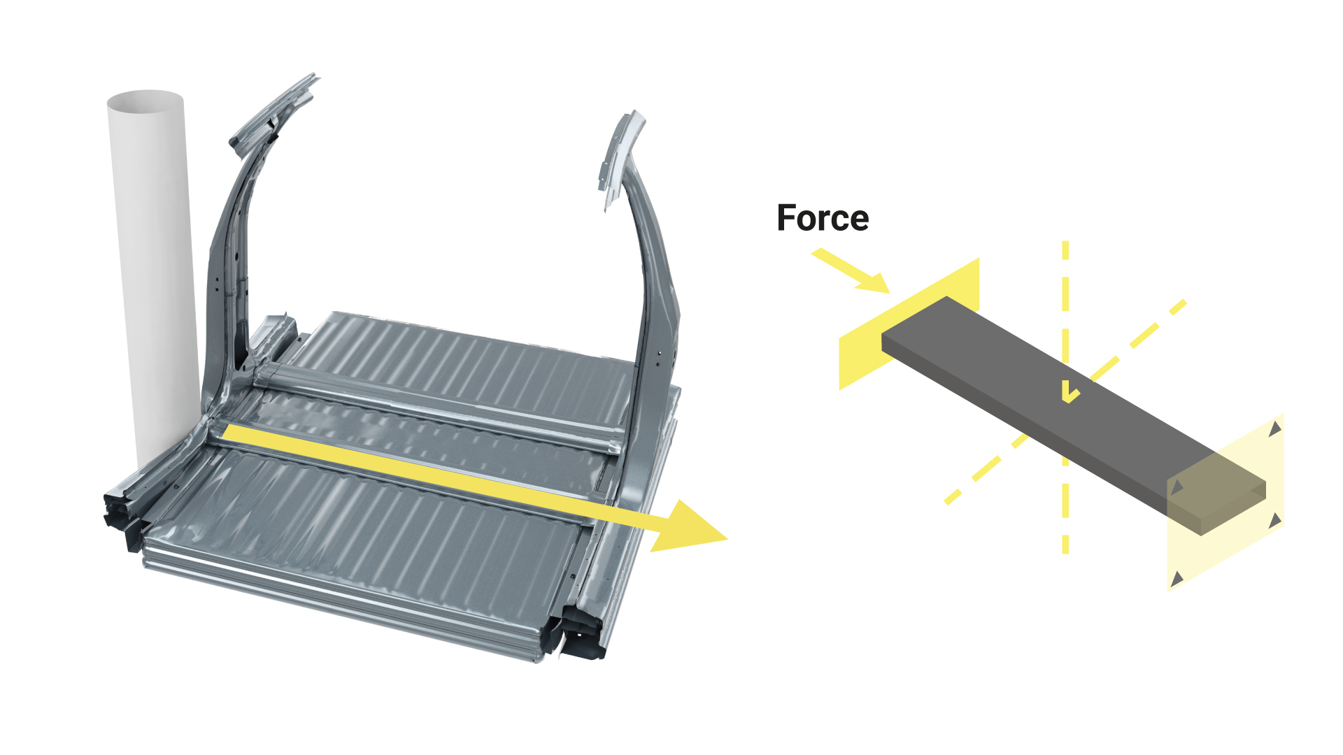
Unlike a car with an internal combustion engine, an EV must absorb more energy through the car’s sill. Why? 1) The weight of the EV’s battery, 2) the EV’s stiffer underbody, and 3) the requirement that no intrusion whatsoever is allowed into the EV’s battery pack. Extruded aluminum in the sill has been seen as an efficient way of absorbing higher energy levels, but at a price premium.

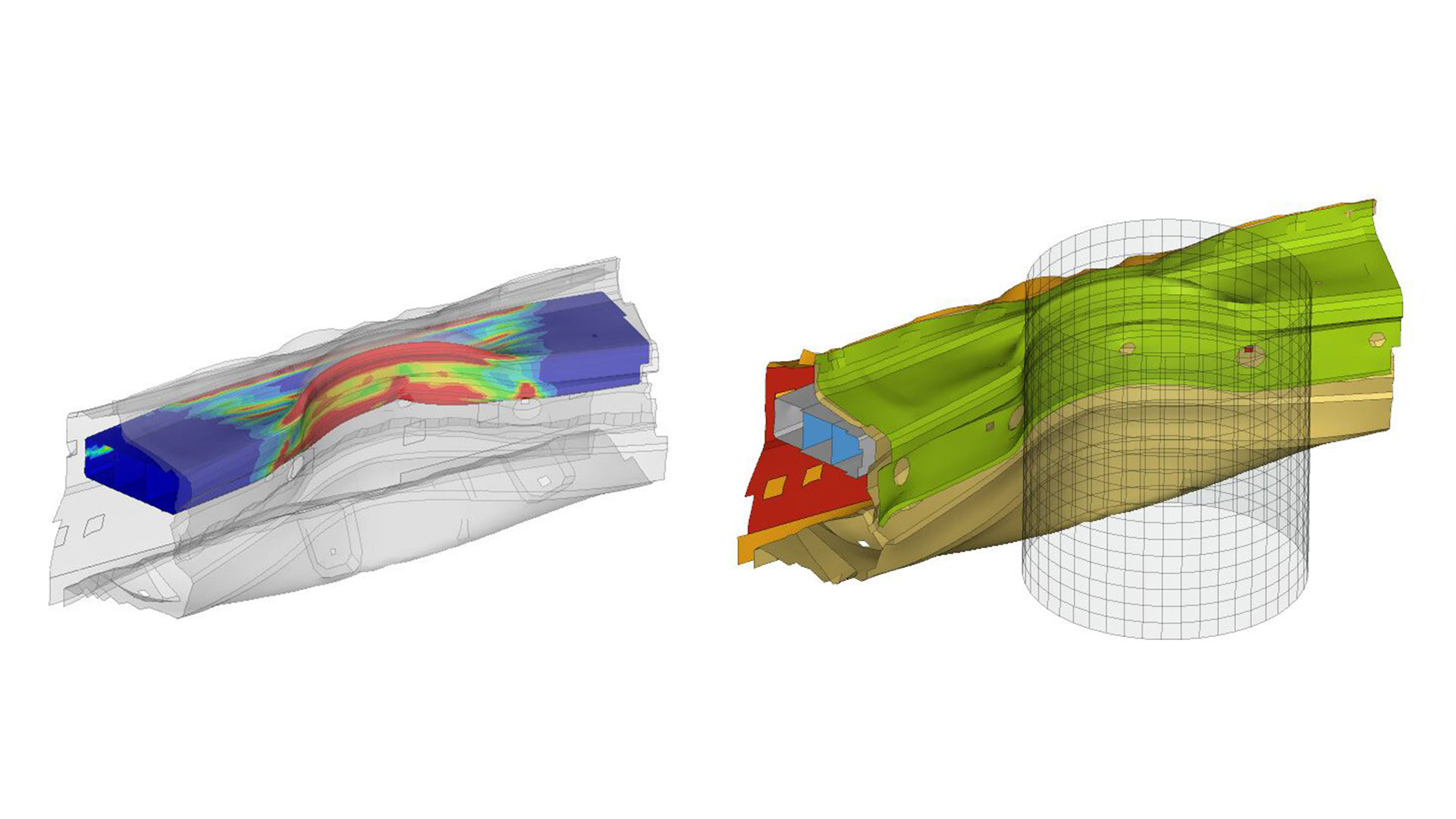
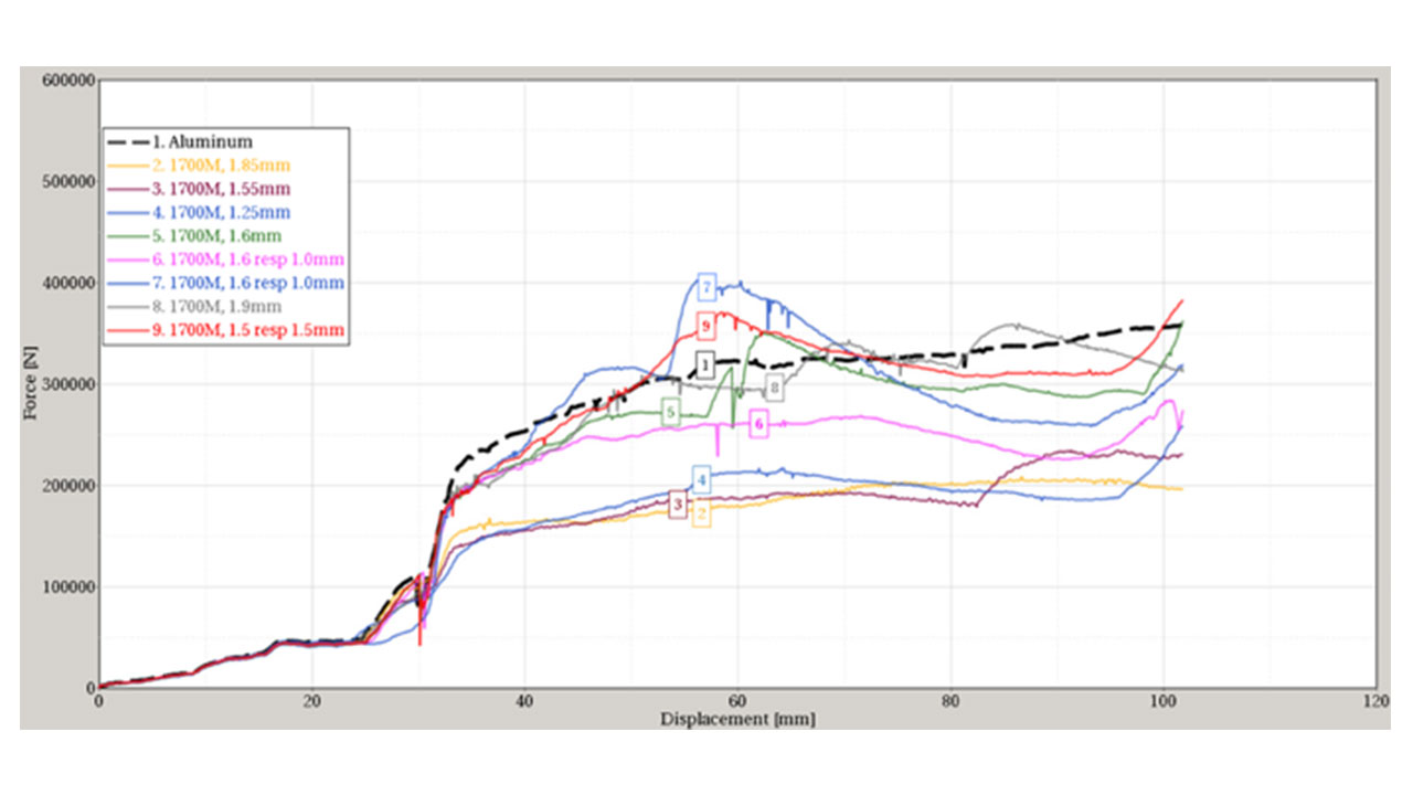
To try match the performance of extruded aluminum sill beams, SSAB has run simulations for 2D roll-formed sill beams made from Docol CR 1700M steel. The extruded aluminum alloy is EN AW-6082 T6, with a thickness of 4.5mm for the outer walls and 3mm for its ribs.

The number of possible designs for 2D roll forming the sill beams are endless, so the results in Figure 6 only show some of the typical designs. (Many more sill beam profiles have been simulated by SSAB but are not shown here.)

Simulation of side pole impact test on EV sill/rocker panel in 1700M
Figure 5: Simulation of side pole impact test: the pole pushes into the sill structure where its Docol CR 1700M beams must prove their energy-absorbing effectiveness.

Testing EV sill/rocker profiles made from 1700 martensitic steel

Figure 6: Plotting force vs. displacement for nine different Docol 1700M profiles for beams used in an EV’s sill/rocker structure. To see the profiles of the sill beams tested here, including the best performing profile, contact Docol.

The wall thickness for each design profile is adjusted so the weight of the Docol 1700M sill beam is the same as the 6082 T6 aluminum sill beam.

The force vs. displacement simulations show that an AHSS steel cross section must have some sort of rib to work properly. Therefore, all these profiles have some sort of inner structure. To try to keep fabricating costs and complexity down, many simulations have been done using square-shaped tubes welded together.

The welded square tube approach seems to work, but the abutting ribs are doubly thick. And, according to the simulations, the thickness of the outer shell of the profile is more important than the thickness of the ribs.

SSAB has determined which profile – with single-wall ribs – allows for thicker outer walls and delivers a crash performance that is similar to that of an aluminum beam, with the weights being the same for both materials.

Would making an energy-absorbing sill/rocker beam from Docol 1700M AHSS withstand crash deformation without cracking? Initial Docol prototypes show that it can. However, all these square-tube profiles require some type of welding and SSAB needs to perform more testing to determine if the beam’s welds ductile enough to handle deformation without cracking.


Designing AHSS floor cross members for efficient crash load transfer

The most efficient way of protecting the EV’s battery pack from intrusion during a side crash is to ensure that the cross members directly underneath the floor of the passenger compartment do not deform. Therefore, the cross members must be strong and not absorb energy at all – instead, they should transfer the side crash force from one side of the car to its opposite side: see Figure 7.

For the best possible crash performance/weight/cost ratio, cross members must be made from thin sheet AHSS steel, which can be a challenge when the steel in used in compression. (See Design Handbook: Structural design and manufacturing in high strength steel.)

Cross beams with different profiles – but all made with Docol CR 1700M – have been simulated by SSAB and there is a huge difference in performance. Starting with a square-shaped profile, one question is how big the radius should be. Is a big radius with a moderate and more spread-out work hardening area better than small radius with a high but very localized work hardening area? The simulation results below in Figure 8 show that 15xt (radii in mm times thickness of the cross member) performs better than 1xt. The Docol 1700M thicknesses of the cross member have been adjusted so the overall weight of the different beam profiles is the same.

Side crash load path for EV cross members in 1700M

Figure 7: Left image: Side crash load path through floor cross member. Right image: Set up of cross member optimization.

Force displacement of EV cross members in 1700 martensitic steel
Figure 8: Force displacement curves of the simulated Docol CR 1700M cross members. The labels show the radii in mm times thickness of the beam. To see the profiles of the cross member beams tested here, including the best performing profile, contact Docol.

AHSS steels have a very high yield point and therefore the phenomena called “local buckling” must be considered for wide and thin parts that work in compression: see SSAB’s Design Handbook. One way of restraining local buckling is to make the wide segments of a profile less wide by means of a groove and increasing the level of material utilization.

Obvious in Figure 8 is that: 1) a large radius is better than a small radius, and 2) that grooves have a major effect by eliminating local buckling – they provide more radiuses through which forces can travel. Notable is that a profile which has one or more grooves is actually larger by surface area and has to have a thinner gauge Docol 1700M in order to keep the same total weight.

The simulation results show that an optimized cross member can more than double the crash load transfer performance over the square-shaped profile. What is critical in this application is the peak load, not the energy absorption. In an event of a crash, this peak load must not be exceeded.


What’s next for the Docol EV Design Concept?

We want to appeal to OEMs’ self-interest, motivating them to use AHSS steels for critical components in battery electric vehicles – while achieving the same weight savings as higher-priced aluminum or other CO2-intensive materials.

We also want OEMs to achieve higher levels of AHSS material utilization so they can realize additional savings. We’ll provide auto designers with AHSS simulations, such as the side crash simulations, that show how to improve the performance of critical safety components, like improving the performance of floor cross members by a factor of two.

And finally we want to demonstrate innovative new designs and production methods for AHSS steels, such as 3D roll-forming for more space-efficient EV battery boxes. Innovations like 3D roll-forming AHSS to fabricate cross meshes that work under compression will really open up the way designers think about achieving maximized axial load performance – both lateral and longitudinal.

Do you have a BEV design challenge that you would like to solve using AHSS steels? It’s never too early to contact us for your next project.