Problem-solving approaches to AHSS edge ductility
The formed cut edges of advanced high-strength steels (AHSSs) require sufficient edge ductility, otherwise they can fail — with edges cracking along holes or flanges.
The formed cut edges of advanced high-strength steels (AHSSs) require sufficient edge ductility, otherwise they can fail — with edges cracking along holes or flanges.
This article discusses how AHSS edge cracking can originate in both the cutting and forming processes — and the best practices for cutting, tooling, and material testing so as to reduce edge failures. The article covers the highlights from a recent Docol® Edge Ductility webinar with Vili Kesti, Senior Forming Specialist at SSAB.
In general, edge ductility is needed whenever cut edges are formed. For example in automotive chassis applications, parts are often mechanically sheared or punched in a serial production process. After cutting there are lots of different edge-straining situations: for example, hole-expansion, collar forming, flange stretching, and so on.
As designs become more complex for AHSS automotive parts, forming crack-free cut edges can become an increasingly challenging process — especially for hot-rolled AHSS steels. And a part’s fatigue properties can also be adversely affected if edge areas have initial defects like cracking.
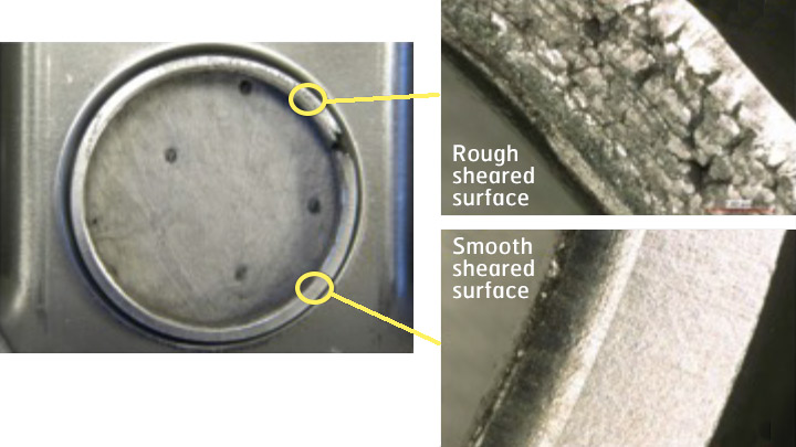
This is a typical problem: a crack has occurred on the hole’s edge during the hole expansion process. The crack started in a section of the hole’s circumference that displays a rough sheared surface.
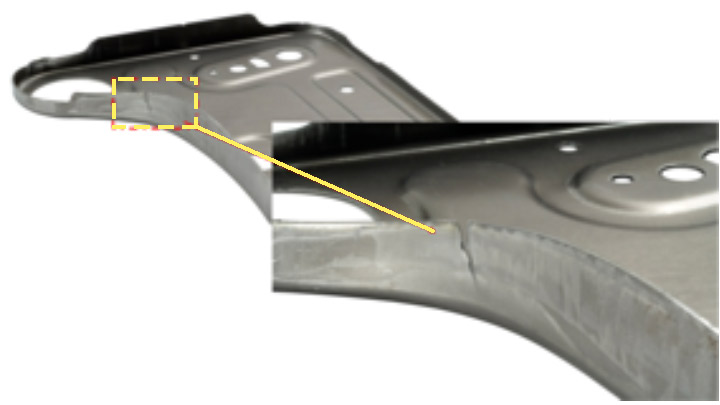
Another example: here’s a close-up of a typical flange crack in an area where large tensile strains were introduced during forming.
Simulation software can be very effective in catching critical areas (i.e., high strains) that initially may not be obvious candidates for cracking.
Mechanical cutting processes, like hole-punching, introduce intense work-hardening as well as possible initial voids and burr formation along cut edges — all of which create a “shear affected zone” or SAZ.
SSAB has taken microhardness measurements and determined that the closer to the cut edge face we go, the higher the work-hardened values. This reduces the deformation capacity of the edge even before any forming process.
SAZ voids can be created in the vicinity of inclusions, carbides, phase boundaries, etc., depending on the microstructure of the AHSS.
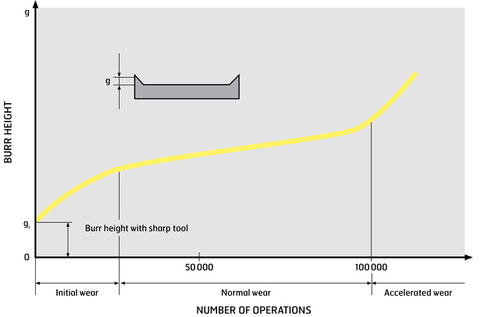
The first best practice during forming is to know (and chart) your tool wear rate. Typically you get an initial wear rate, then a plateau, then an accelerated rate. A similar pattern usually occurs for burr formation: see chart. In both cases, maintain your tooling before the anticipated acceleration begins. Worn tools can profoundly reduce hole expansion ratios (HERs) for some AHSS grades.
When possible, place your burr on the inside of an edge. Burrs on the outside of an edge tend to create defects during subsequent bending operations.
Using the optimal cutting clearance for a specific AHSS grade — which in some cases is higher than ISO 16630 HER standard of 12% — can increase your HER values. Check with your AHSS producer for cutting clearances for a specific grade and application.
Maintaining tools and consistent cutting clearances are interrelated. Tool wear is affected by both the cutting clearance and the AHSS grade you are cutting. Tool stiffness is also important: stiffness helps deliver consistent cutting clearances around holes and along longer flanges.
The shear affected zone can be eliminated by changing your cutting method to drilling, machining, or wire cutting (EDM). Unfortunately, drilling, machining and EDM are time-consuming and not viable for large production runs. Thermal cutting methods like laser or plasma can improve edge ductility, but they can create hardness gradients due to their heat.
Many technical papers provide evidence that pre-piercing, also known as two-stage shear cutting, can significantly improve AHSS hole-expansion ratios and therefore edge formability.
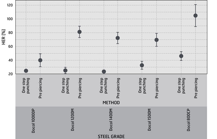
With pre-piecing, a single, stepped punch or two separate punching operations are used to create an initial hole followed by a trimming action. For optimal results, the thickness of the resulting trimmed or punched-out ring must be carefully chosen. Pre-piercing can greatly improve HER, but the amount of improvement varies from grade to grade, as shown on this chart.
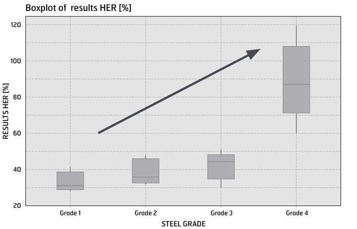
Edge ductility can differ significantly from grade to grade, even when the grades have similar strength levels. You will also notice differences between various steel producers supplying nominally the “same named” grade.
Furthermore, there is no clear correlation between HER and traditional yield strength, tensile strength, or elongation. (That said, recent publications do show a possible correlation between true thickness fracture strains and HER: if additional research confirms this correlation, we hope to write about it in a future INSIGHTS article.)
For example, here are four different steel grades, all with a minimum 800MPa tensile strength. Obviously by choosing the correct steel grade, you can get significant improvements in your edge forming properties.
Another consideration when selecting AHSS steels: in real-life workshop conditions, it can be difficult to keep your cutting clearances consistent. This chart shows how Docol® HE (high edge) grade has better edge quality and better formability over a range of cutting clearances when compared to traditional AHSS grades.
![Boxplot of HE-ratio S355MC vs Docol 355 HE different clearances [%]](/-/media/images/docol/automotive-insights/2021/720x461-diagram4.jpg?m=20210326100449)
The current worldwide standard for hole expansion testing is ISO 16630, which has been widely criticized for delivering results with excessive uncertainty and variation.
ISO 16630 only covers one specific stress/strain state. But real-life production often includes different edge-loading cases. Even in the same automotive part, there can be a variety of different stress/strain states for the edges.
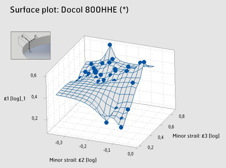
We can utilize different tests to cover a wider range of stress/stain loading cases, including online digital image correlation (DIC) strain measurements. SSAB’s researchers use:
SSAB researchers are working on a new concept to describe “overall edge formability.” The approach uses all of the tests listed above to test an AHSS sample in three different directions (ε1, ε2, and ε3) to create a 3-dimensional edge forming limit diagram (FLD), plotting the strain limits just before cracking.
3-dimensional edge forming limit diagrams are a good way to visually compare different materials and their overall edge ductility. There is also the possibility that they could be effectively used in simulations: stay tuned.
Or do you have questions about determining edge ductility for a specific AHSS grade and automotive parts application?
AHSS cut edges and formed cut edges require sufficient edge ductility, otherwise they can fail by cracking along hole edges or along flange edges. In this webinar, Vili Kesti, from SSAB's Knowledge Service Center, explores how edge cracking can originate in both the cutting and forming processes — and what cutting and tooling approaches can reduce AHSS edge failures.

High edge ductility HSLA steel with greatly improved local formability and high hole expansion ratios – ideal for challenging auto components with complex designs on sheared stretched edges.

Want to discover unique automotive applications for AHSS materials? Try new production methods? Or create lighter components that can improve fuel efficiency, crash-worthiness and sustainability?
Subscribe to our free, monthly Automotive Insights newsletter and receive relevant, in-depth articles about the issues affecting your business and invitations to our webinars.